The circuit shown in the figure below uses ideal positive edge-triggered synchronous J-K flip flops with outputs X and Y. If the initial state of the output is X =0 and Y =0 just before the arrival of the first clock pulse, the state of the output just before the arrival of the second clock pulse is
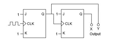
- X=0, Y=0
- X=0, Y=1
- X=1, Y=0
- X=1, Y=1