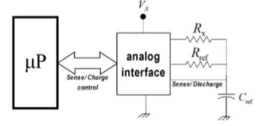
In the microprocessor controlled measurement scheme shown in the figure, $R_x$ is the unknown resistance to be measured, while $R_{ref}$ and $C_{ref}$ are known. $C_{ref}$ is charged from voltage $V_L$ to $V_H$ (by a constant DC voltage source $V_s$), once through $R_{ref}$ in $T_{ref}$ seconds and then discharged to $V_L$. It is again charged from voltage $V_L$ to $V_H$ through $R_x$ in $T_x$ seconds.
If $T_x=kT_{ref}$ then
- $R_x=kR_{ref}(1-\frac{V_L}{V_H})$
- $R_x=kR_{ref}ln(\frac{V_H}{V_L})$
- $R_x=kR_{ref}$
- $R_x=kR_{ref}\;ln\;k$