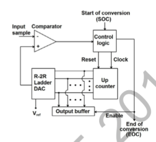
The circuit in the figure represents a counter-based unipolar $ADC$. when $SOC$ is asserted the counter is reset and clock is enabled so that the counter counts up and the $DAC$ output grows. When the $DAC$ output exceeds the input sample value, the comparator switches from logic 0 to logic 1, disabling the clock and enabling the output buffer by asserting $EOC$. Assuming all components to be ideal, $V_{ref}\; DAC$ output and input to be positive, the maximum error in conversion of the analog sample value is:
- directly proportional to $V_{ref}$
- inversely proportional to $V_{ref}$
- independent of $V_{ref}$
- directly proportional to clock frequency