Consider the logic circuit with input signal $\text{TEST}$ shown in the figure. All gates in the figure shown have identical non-zero delay. The signal $\text{TEST}$ which was at logic $\text{LOW}$ is switched to logic $\text{HIGH}$ and maintained at logic $\text{HIGH}$. The output
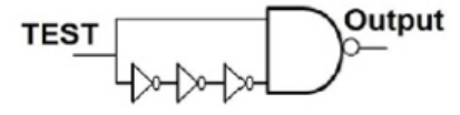
- stays $\text{HIGH}$ throughout
- stays $\text{LOW}$ throughout
- pulses from $\text{LOW}$ to $\text{HIGH}$ to $\text{LOW}$
- pulses from $\text{HIGH}$ to $\text{LOW}$ to $\text{HIGH}$