The clock frequency of the digital circuit shown in the figure is $12 \: \mathrm{MHz}$. The frequencies of the output $(\mathrm{F})$ corresponding to Control $=0$ and Control $=1$, respectively, are
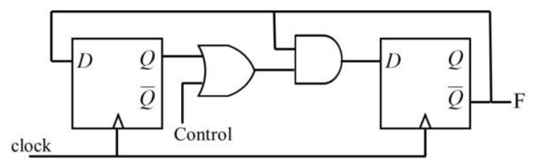
- $4\: \mathrm{MHz}$ and $6\: \mathrm{MHz}$
- $6\: \mathrm{MHz}$ and $4\: \mathrm{MHz}$
- $3\: \mathrm{MHz}$ and $4\: \mathrm{MHz}$
- $3\: \mathrm{MHz}$ and $6\: \mathrm{MHz}$
